Game Environment Modeling: Plarium’s Soldiers Inc
Maxim Kabat, Plarium Kharkiv’s 3D Art Team Lead, shares with us his experiences modeling buildings for Plarium’s Soldiers Inc: Mobile Warfare.
Project Goals
We decided to create a project in a completely new setting. Basically, we had to do three things. First, develop a common concept design for all buildings located in a player’s sector and on the global map. Second, create designs for every single building, and third, optimize these designs for the Unity engine.
Soldiers Inc: Mobile Warfare has a futuristic military setting. The action takes place 20–30 years from now, yet it is not a futuristic sci-fi game. It was definitely a challenge to convey the kind of atmosphere we wanted.
Difficulties
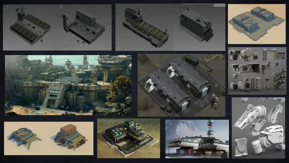
The main difficulty we faced when we started collecting references was the lack of relevant art and material. It’s easy to find references for such popular settings as fantasy, medieval, or pure sci-fi, since there are lots of movies and games dedicated to these settings.
But we could barely find anything for our futuristic military setting. Here are some examples of artwork we did manage to find:
Creating the Concept Design
Some of the initial sketches were created by our Concept Artist Oleksandr Dudar, who I am very grateful to. He used simple yet versatile shapes.
All concept designs feature a common idea: buildings should be mobile and easy-to-deploy in the field. For example, a module box dropped from a helicopter should be able to transform into a fully-featured wellhead. Mobility became one of the fundamental design principles for all the buildings in the game. Based on the above, we moved to create concept designs for the main buildings.
Finding Ideas
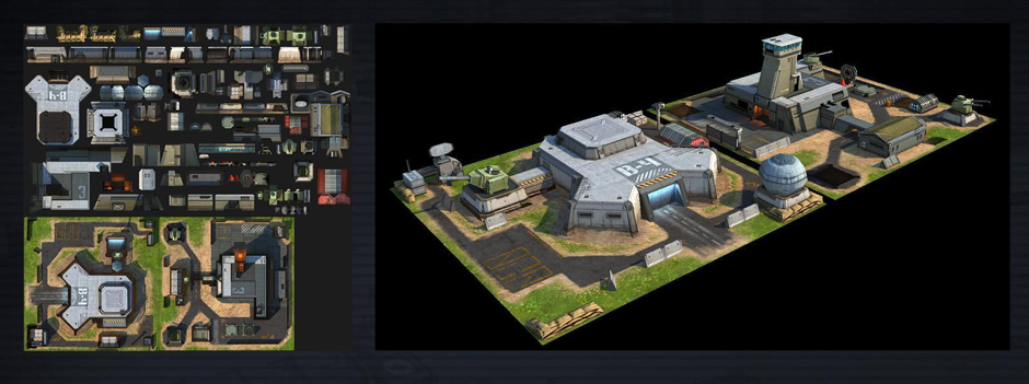
My regular approach is very simple. It boils down to three main steps: finding simple forms, selecting a color palette, and working out the details. For example, here is how I created the control tower:
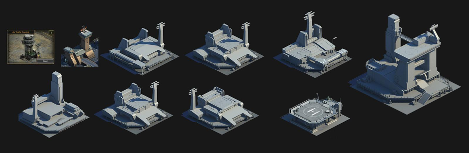
1. I started with blocks and masses. Usually I create these using simple cubes in Maya. What I needed to develop at this point was a key feature of a building. It had to be the biggest, the simplest, and the most recognizable building part.
2. I chose a couple of the most appropriate concepts in order to test my color palette. For testing purposes I usually use three colors. In the case of the control tower I used gray – a standard color for this setting – khaki, and blue or orange, all depending on particular elements. It was also possible to use 2 or 3 different tones of one color to dim or highlight certain parts of a building.
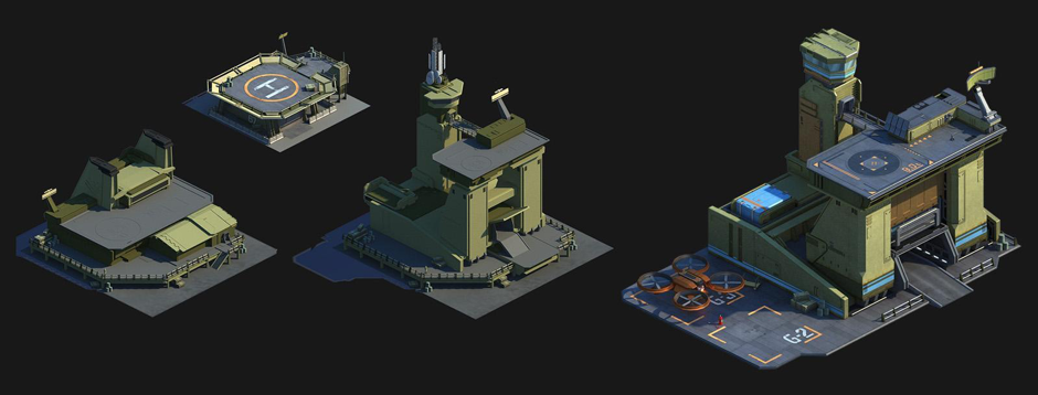
Of course, a colored concept (left) still differs from the final version (right). A model may go through numerous improvements before its final rendering.
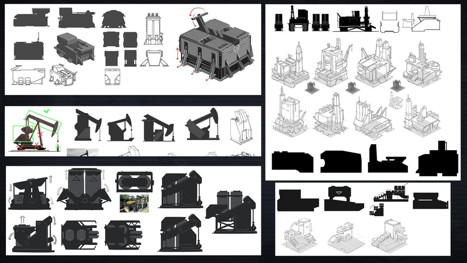
Sometimes it takes around a week to find a proper idea, as was the case with the Supply Depot.
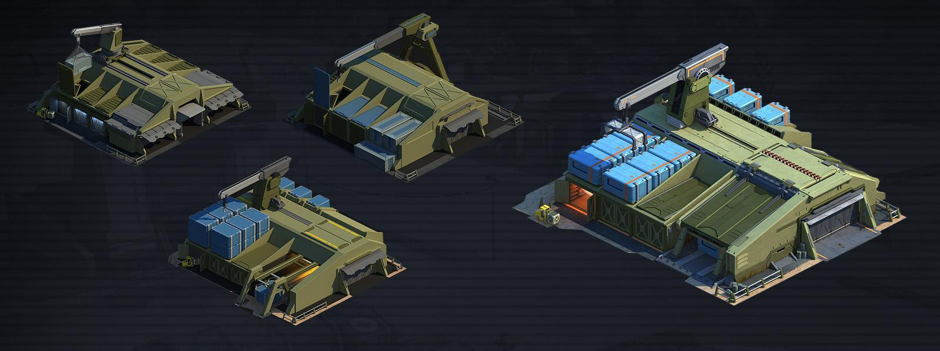
You can see on the image above all the modifications the crane went through over its various iterations. At first the crane was too small, then too large. Eventually, I settled on something between those two. I also decided to make the building asymmetrical. A bit of vivid blue helped me to highlight some of the key elements.
Sometimes you need to create a bunch of concepts in order to get a desired shape. Take a look at this Aid Center:
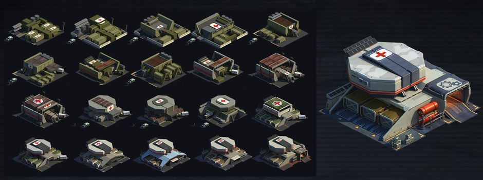
If you follow all the updates from left to right and top to bottom, you will see the idea evolving. Initially I wanted this building to be a series of interconnected containers. I made several attempts to elaborate on this idea before I finally came up with a feature that I really liked: a large octagonal roof. It took several more iterations to refine this feature and get a final version.
Peculiarities in drafting concepts
There are quite a few peculiarities. For example, a building’s function should be clear from its design. And if you are planning to animate it, you need to do so after you start drafting your concept. It looks great when 30–40% of a building is animated.
As you can see in the presentation, some of the buildings we made can open and display what is going on inside. Impressive animation must be robust and noticeable. It should involve multiple moving elements. If your animation comes down to a tiny unit walking back and forth across the roof, it is not going to impress anyone.
Software
I use standard Maya tools like Insert Loop, Extrude, Bevel, and Chamfer. Nothing special here. First of all, I choose a couple of concept designs for a certain building. Then I use them as a reference to create a high-poly model.
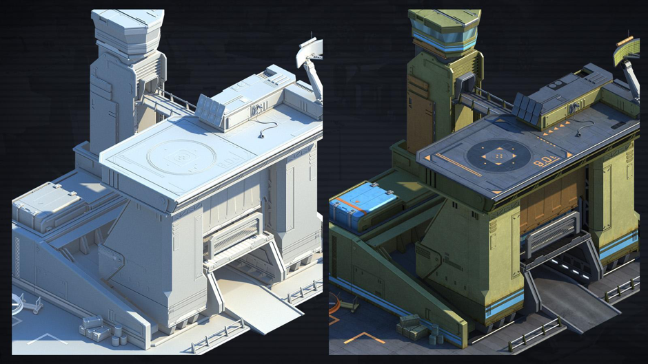
I try to model every detail as much as I can. The following image shows how detailed these models are.
As you can see on the left, even the numbers and stripes are made with geometry. It’s slightly shifted from the main surface and has a transparent material applied to it. The only things I left for texturing were the tiles on the upper and lower grounds as well as the metal walls.
Modeling takes about one or two days. At this stage I tend to ignore such limitations as the number of polygons or the number and size of textures. What really matters here is a good-looking model. This approach may require a bit more time, but the result it provides is much better than if you follow all those restrictions from the beginning. Of course, we will then have to optimize this model for Unity. But we’ll deal with that later, after creating a low-poly model.
Texturing Approach
I use the material editor in Maya and standard V-Ray materials. Again, nothing special here. However, there are some tricks. For example, I never map the entire building’s geometry. Instead, I work with its separate parts. This way I can still adjust and improve the concept design anytime during the texturing process. In addition, I can move objects and edit their shapes, as well as add and remove details. Let’s say I want to create a generic material which can be used for 40% of all textures. Here’s what I need to do:

Step 1 – Render a simple gray V-Ray material.
Step 2 – Add Ambient Occlusion to it, using V-Ray Dirt map. This map darkens some of the object joints.
Step 3 – Apply Dirt again, but now inverted.
Step 4 – Add a gradient. Project it to the entire geometry so that the bottom of the building is darker. As a result, you will see the building visually grow in size.
Step 5 – Blend this material with a tile texture using Multiply.
Step 6 – Add a material property. For example, if I want some gloss on my metal material, I need to add a diffuse texture and desaturate it. I then increase the contrast and add the resulting two textures to the main material as Specular and Bump. As a result, we get a texture and a gloss.
The mapping is done automatically. It adjusts to the tile textures of the wall.
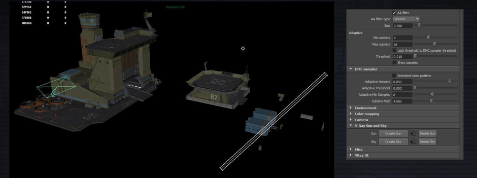
Rendering & Converting
I use Maya for rendering. The operation is quite standard. Since this is an outside render, I use V-Ray Sun as a light source. Sometimes I use Ambient lighting. When I need to highlight certain elements, I use additional light sources. I actually did this in order to illuminate the quadcopter.
Having rendered a high-poly model, I then make a low-poly copy of it. To do so, I build a new model on top of it using standard polygons. Later we will bake a low-poly model from a high-poly render.
And here’s when the number of polygons becomes important. I also need to determine which elements of the model can be reused and which ones are going to be unique. I then do UV mapping of the low-poly geometry; it’s necessary for baking. After, I select the low-poly element in the same scene where I rendered my high-poly model and bake it using the V-Ray Bake function. The Projection Baking option should be checked. This way, all the building elements are baked one after another.
I always start with high-poly modeling. It’s a handy way to get a low-poly model with the high-poly level of detail. It also lifts any restrictions on modeling and texturing. And besides, it’s not really convenient to create small elements right off in low-poly.
Mapping & Baking
I usually do this in two steps. When you bake it for the first time, it’s hard to guess which elements are going to be reused and which ones will remain unique.

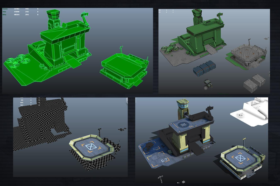
For example, the building on this image doesn’t have its left part, since it was reasonable to simply reflect the right part of it. At the same time, you can see on the map that I baked the roof three times: by parts, in camera view, and in top-down view. As a result, I used the combination of these three options.
This map is a draft, so for now it doesn’t really matter how it looks.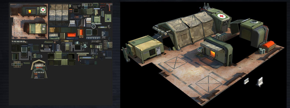
In this example I only mapped 2 elements of the fence. Then I used them to construct the whole row. As you can see, the texture is really raw and has lots of space between UV shells. Another example of a map draft:
The next step was to piece the building together, patch all the holes or blank spaces, and duplicate repeating elements. After that I made a clean UV map and put UV shells on it as densely as possible. Next, I used the standard Transfer Maps tool to move the textures from the draft UV to the clean one.
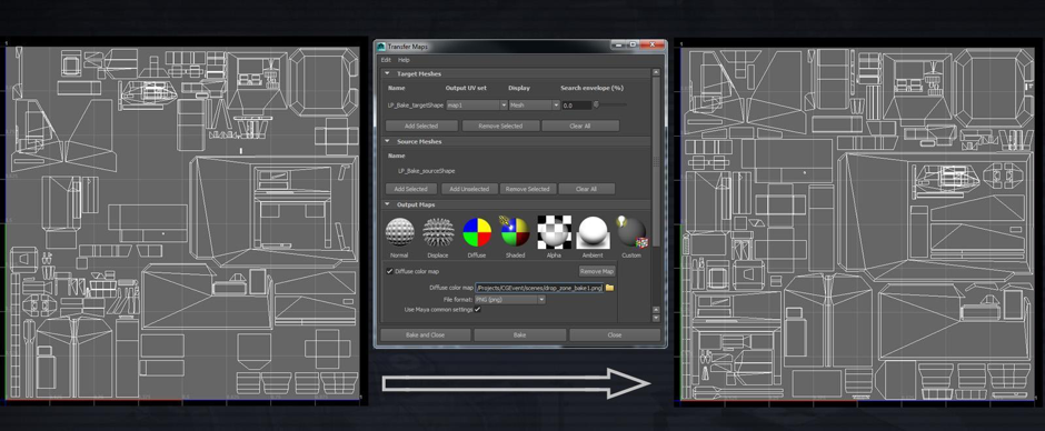
In the end I got a ready low-poly model with a very precise UV map and no errors, holes, or blank spaces.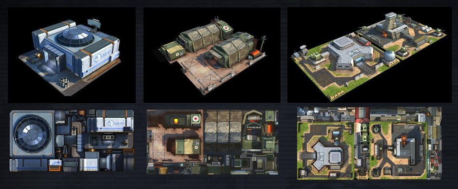
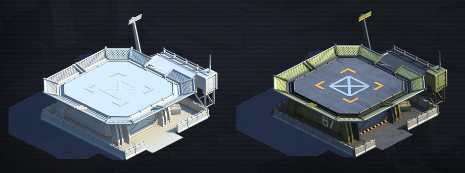
This is the final view of the buildings – the assembled low-poly models with clean texture maps baked on them. Each one looks pretty neat considering it’s low-poly.
Importing Models into the Game
Our engine, Unity, has certain limits we need to consider before importing. For instance, draw call limits for mobile devices. Simply said, all the objects on a screen with a single material assigned to them can be drawn in one draw call. And since draw calls are limited in number, we try to use them as little as possible. Therefore, we need to compile all textures in one texture atlas.
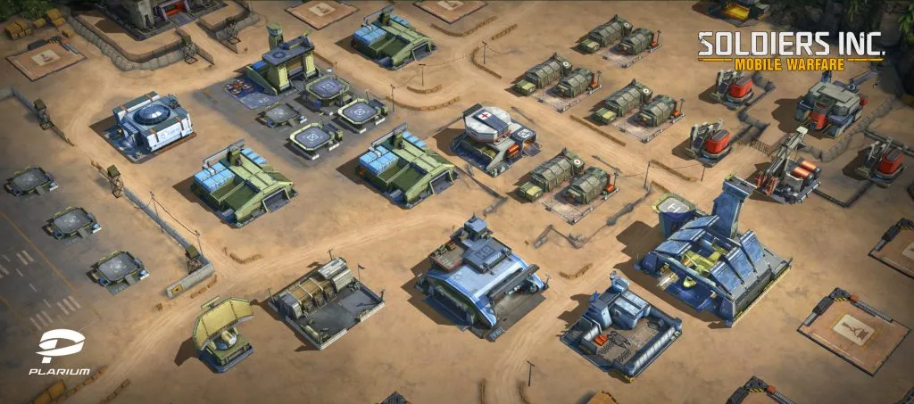
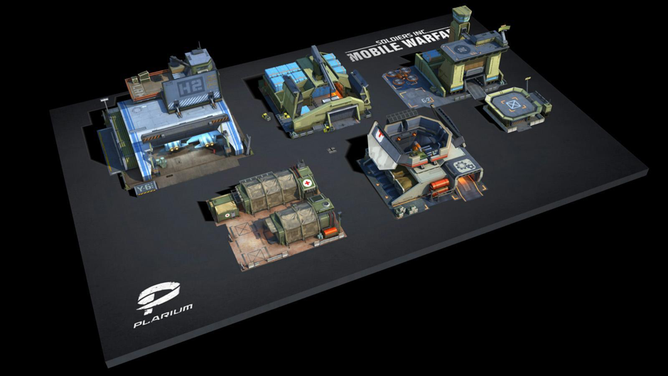
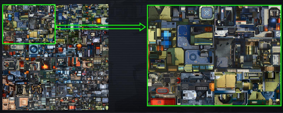
And here’s how everything finally looks on the screen of your mobile device:

Thanks for reading!